First up, we got a function generator built around the trusty 555 timer IC. This lil' chip is a real workhorse, man. You can use it for all kinds of stuff, and in this case, it's pumpin' out square, triangle, and even sine waves. Think about it – you can test audio equipment, simulate signals, troubleshoot circuits… the possibilities are endless! You ain't gotta be a rocket scientist either, the circuit is relatively simple, meaning you can tinker with it, tweak it, and really understand how it works. That's how you truly learn, you know? Hands-on experience, building and experimenting. So ditch the simulator, grab a breadboard, and let's get to work!
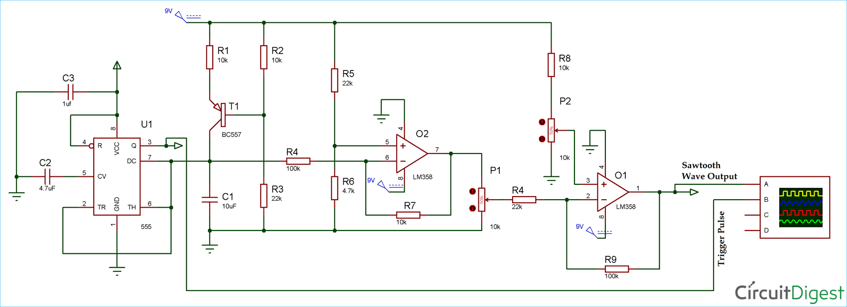
Function Generator Circuit Using 555 Timer

This diagram right here is your roadmap. See those resistors and capacitors? They ain't just there for decoration. They control the frequency and shape of the waveforms. Mess with those values and you can change the output. Experiment, take notes, and see what happens! Don't be afraid to blow a capacitor or two; that's how you learn what *not* to do next time! Understanding the relationship between these components is key to understanding how electronics work in general. Plus, building something like this from scratch, troubleshooting it, and finally getting it to work properly? That feeling is priceless. You'll feel like a straight-up wizard.
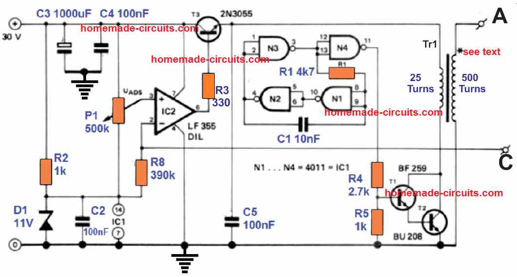
Now, let's switch gears and talk about pulse generators. Sometimes you don't need fancy sine waves or triangle waves; sometimes you just need a good, clean pulse. That's where this next circuit comes in. This one uses CMOS ICs, which are known for their low power consumption. That's important if you're building battery-powered devices, or just trying to be a little eco-friendly (you know, saving the planet, one circuit at a time!). A pulse generator is useful for all sorts of applications, from timing events to triggering other circuits. It's like the heartbeat of your project, keeping everything in sync.
One Pulse Generator Circuit Diagram

Take a look at this schematic. Again, it looks a bit intimidating at first, but break it down into its individual parts and it's not so bad. You'll see gates and timing elements – the building blocks of digital logic. The neat thing about this circuit is its simplicity. It shows that you don't always need a ton of fancy components to accomplish a task. Sometimes, the most elegant solutions are the simplest ones. So, whether you're a seasoned engineer or just starting out, these projects are a great way to hone your skills and learn something new. Now go on and build something amazing!
If you are searching about AVR GB-130 Brush Generator AVR Circuit Diagram GB130 for Diesel Engine you've visit to the right page. We have 25 Pictures about AVR GB-130 Brush Generator AVR Circuit Diagram GB130 for Diesel Engine like generator circuit diagram - Circuit Diagram, Signal Generator Circuit Diagram and also AVR GB-130 Brush Generator AVR Circuit Diagram GB130 for Diesel Engine. Here you go:
AVR GB-130 Brush Generator AVR Circuit Diagram GB130 For Diesel Engine
 partsofgenerator.com
 Signal Generator Circuit Diagram
 www.circuitdiagram.co
 Circuit Diagram Of Function Generator
 wirepartnotaryship.z22.web.core.windows.net
 Emp Generator Circuit Diagram - Wiring Diagram
 www.diagramelectric.co
 Marx Generator Circuit Diagram
 schematicguides.z21.web.core.windows.net
 Impulse Generator Circuit Diagram
 enginelibsacrists.z21.web.core.windows.net
 Free Energy Generator Circuit Diagram
 circuitpiekfeinbd.z21.web.core.windows.net
 [DIAGRAM] Circuit Diagram High Voltage Generator - MYDIAGRAM.ONLINE
![[DIAGRAM] Circuit Diagram High Voltage Generator - MYDIAGRAM.ONLINE](https://www.rlocman.ru/i/Image/2010/12/05/High-volt-genarator-circuit.gif) mydiagram.online
mydiagram.online Sine Wave Generator Circuit Calculator - Circuit Diagram
 www.circuitdiagram.co
 Understanding The Circuit Diagram Of A Generator: A Comprehensive Guide
 eleccircs.com
 Circuit Diagram Waveform Generator Voltage-controlled Triangle Wave
 ecircuitdiagrams.blogspot.com
 Circuit Diagram 3 Bit Parity Generator - Vrogue.co
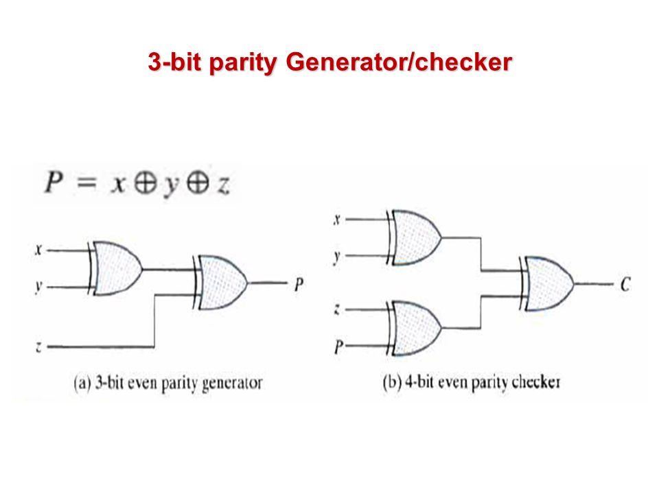 www.vrogue.co
 Generator Circuit Diagram - Circuit Diagram
 www.circuitdiagram.co
 Function Generator Circuit Diagram Using 555 Timer - Circuit Diagram
 www.circuitdiagram.co
 Simple Emp Generator Circuit Diagram
 guidelisthihellenizes.z14.web.core.windows.net
 Icl8038 Function Generator Circuit Diagram
 www.circuitdiagram.co
 One Pulse Generator Circuit Diagram
 userdiagramkoler99.z19.web.core.windows.net
 High Voltage Generator Circuit Diagram Circuits Proje - Vrogue.co
 www.vrogue.co
 Audio Signal Generator Circuit Diagram
 www.circuitdiagram.co
 Single Phase Generator Circuit Diagram
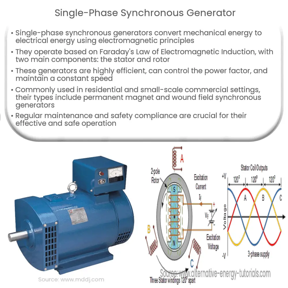 guidefixpolujanobc.z22.web.core.windows.net
 Circuit Diagram Of Function Generator
 usermanualtractors.z1.web.core.windows.net
 Triangle Wave Generator Circuit Diagram - Circuit Diagram
 www.circuitdiagram.co
 AVR GB-130 Brush Generator AVR Circuit Diagram GB130 For Diesel Engine
 partsofgenerator.com
 [DIAGRAM] Caterpillar Generator Circuit Diagram - MYDIAGRAM.ONLINE
![[DIAGRAM] Caterpillar Generator Circuit Diagram - MYDIAGRAM.ONLINE](https://lh3.googleusercontent.com/blogger_img_proxy/AEn0k_uXOSf1AJUuGHBCnPwTk6EuimxgthJo_5X5gQtCduJMtwfeVdLtlD0qmAYT8wxp9BJUMQsZ9wOhHL91yQfO6y2TlZshO0wssB8kRnmcQEJ3S-Rk2E_ADSRsKvK1F8CNbiT2FAEkMPWDVnr0kNkqJUSvktQBlJLX2lQ=s0-d) mydiagram.online
mydiagram.online Sine Wave Generator Circuit Using 555 - Circuit Diagram
 www.circuitdiagram.co
 Triangle wave generator circuit diagram. [diagram] caterpillar generator circuit diagram. Circuit diagram 3 bit parity generator


